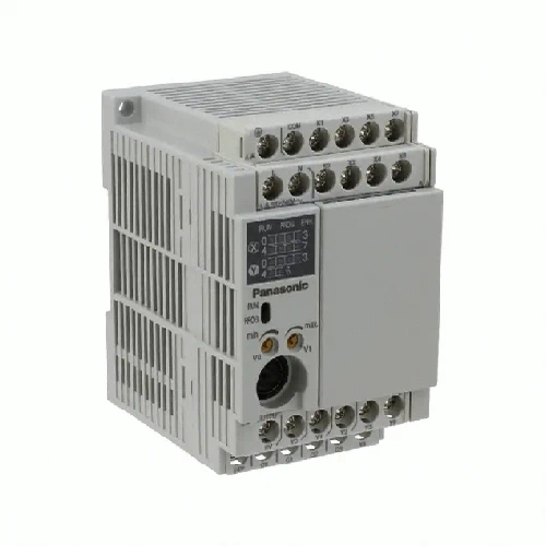
FP-X Control Unit – Panasonic
USD $ 178.20 – USD $ 776.60
Out of stock
SKU: N/A
Specifications-Programmable Controllers / Interface Terminal
| Item | Description | ||||
|---|---|---|---|---|---|
| C14 | C30 | C60 | |||
| Number of controllable I/O points |
Control unit | Relay output type | DC input: 8, relay output: 6 | DC input: 16, relay output: 14 | DC input: 32, relay output: 28 |
| Transistor output type | DC input: 8, transistor output: 6 | DC input: 16, transistor output: 14 | DC input: 32, transistor output: 28 | ||
| Max. I/O points when expanded | 254 points (328 points max. when using add-on cassettes and FP0R expansion units) |
270 points (352 points max. when using add-on cassettes and FP0R expansion units) |
300 points (382 points max. when using add-on cassettes and FP0R expansion units) |
||
| Programming method / Control method | Relay symbol / Cyclic operation | ||||
| Program memory | Built-in flash ROM (no backup battery required) | ||||
| Program capacity | 16 k steps | 32 k steps | 32 k steps | ||
| Number of instructions |
Basic instructions | 89 | |||
| High-level instructions | 226 | ||||
| Operation speed | Basic instruction: 0.32 μs~/step | ||||
| I/O refresh + base time | 0.2 ms [When using FP0R expansion units: 1 ms + (1.5 × Number of expansion units) ms] | ||||
| Operation memory | Relay | External inputs (X) | 1,760 points (The actual usable number of points is restricted by the hardware.) | ||
| External outputs (Y) | 1,760 points (The actual usable number of points is restricted by the hardware.) | ||||
| Internal relay (X) | 4,096 points (R0 to R255F) | ||||
| Special internal relay (R) | 192 points | ||||
| Timer / counter (T/C) | 1,024 points: timer capable of counting (1 ms, 10 ms, 100 ms, 1 sec.) × 32,767, Counter capable of counting 1 to 32,767 | ||||
| Link relay (L) | 2,048 points | ||||
| Memory area |
IMemory area Data register |
-12,285 words (DT0 to DT12284) | 32,765 words (DT0 to DT32764) | ||
| Special data register (DT) | 374 words | ||||
| Link register (LD) | 256 words | ||||
| Index register (I) | 14 words | ||||
| High-speed counter (Note 1) | Built-in (Transistor output): single-phase 8 ch (50 kHz × 4 ch + 10 kHz × 4 ch) Built-in (Relay output): single-phase 8 ch (10 kHz × 8 ch) Pulse I/O cassette: single-phase 2 ch (80 kHz × 2 ch) |
||||
| Pulse output (Note 2) / PWM output | Built-in (Transistor output): 100 kHz × 2 ch + 20 kHz × 2 ch Pulse I/O cassette: One unit (one axis) 100 kHz, or two units (two axes) 80 kHz |
||||
| Time measurement | 10 μs ring counter | ||||
| Potentiometer | 2 points (K0 to K1000) | 2 points (K0 to K1000) | 4 points (K0 to K1000) | ||
| Constant scan | Available | ||||
| Clock / calendar | When AFPX-MRTC is attached: Year (last two digits), month, day, hours (24-hour display), minutes, seconds, day of week. Operates only when a battery is installed. |
||||
| Flash ROM backup |
Backup by P13 commands | Data register (32,765 words) | |||
| Auto-backup at power failure | Counter 16 points (1008 to 1023), Internal relay 128 points (R2480 to R255F), Data register 55 words (C30 / C60 = 32710 to 32764, C14 = 12230 to 12284) |
||||
| Battery backup | The memory allocated in the storage area by the system register (only when a battery is installed) | ||||
| Notes: 1) | Specification at the rated input voltage of 24 V DC, +25 ℃ +77 ℉. Frequency may be lower due to the voltage and temperature. |
|---|---|
| 2) | Max. frequency may vary by the method of operation. Please refer to the manual for details. |


